Humanoid Talker — Build ManualHumanoid Talker — Manual de Armado
A voice-assistant humanoid you build from a Raspberry Pi, a round display, a microphone, and a small speaker. Tap the Talk button in the RobotiMaker app, ask anything, watch the face react. No code on the Pi — the RobotiMaker app takes care of the install for you.Un asistente de voz humanoide que armas con una Raspberry Pi, una pantalla redonda, un micrófono y un altavoz pequeño. Toca el botón Talk en la app RobotiMaker, pregunta lo que quieras y observa cómo reacciona la cara. Sin código en la Pi — la app RobotiMaker se encarga de la instalación por ti.
What's in the boxQué hay en la caja
Four electronic modules, a Pi, and a fistful of jumper wires. That's the whole hardware footprint.Cuatro módulos electrónicos, una Pi y un puñado de cables jumper. Esa es toda la huella de hardware.
You don't need to write codeNo necesitas escribir código
The Raspberry Pi runs a small "bridge" that the RobotiMaker app talks to. Once it's flashed and powered on, the app probes the hardware, installs audio + display drivers, reboots, and provisions the talker software for you. Your job is the wiring.La Raspberry Pi corre un pequeño "bridge" con el que se comunica la app RobotiMaker. Una vez flasheada y encendida, la app sondea el hardware, instala los drivers de audio + pantalla, reinicia y aprovisiona el software del talker por ti. Tu trabajo es el cableado.
Flash the SD card & first bootFlashea la SD y primer arranque
We start headless — no monitor, no keyboard. Flash Pi OS Lite, drop your WiFi credentials into the imager, plug in power, and the Pi joins your network on its own.Empezamos sin pantalla — sin monitor, sin teclado. Flashea Pi OS Lite, mete tus credenciales WiFi en el Imager, enchufa la corriente y la Pi se une sola a tu red.
- Download Raspberry Pi ImagerDescarga Raspberry Pi Imager from raspberrypi.com/software and install it on your laptop.desde raspberrypi.com/software e instálalo en tu laptop.
- Pick the OSElige el SO: Raspberry Pi OS (other) → Raspberry Pi OS Lite (64-bit). "Lite" matters — the desktop version wastes RAM the talker needs."Lite" importa — la versión con escritorio gasta RAM que el talker necesita.
- Click the gear iconHaz clic en el ícono del engranaje in the imager to open advanced settings and fill in:en el imager para abrir los ajustes avanzados y rellena:
- Hostname:Hostname:
byr-talker - SSH: enabled, password authenticationSSH: habilitado, autenticación por contraseña
- Username:Usuario:
byr, password: anything memorablecontraseña: algo que recuerdes - WiFi SSID + password (the same network the RobotiMaker app will use)SSID + contraseña de WiFi (la misma red que usará la app RobotiMaker)
- Locale: your timezone, keyboard layoutLocale: tu zona horaria y disposición de teclado
- Hostname:Hostname:
- Write the SD cardEscribe la SD (5–10 minutes), then eject it.(5–10 minutos), luego expúlsala.
- Insert the SD card in the Pi, plug in powerMete la SD en la Pi y enchufa la corriente. First boot takes 60–90 seconds. The green activity LED flickers steadily while the OS expands the partition.. El primer arranque toma 60–90 segundos. El LED verde de actividad parpadea de forma constante mientras el SO expande la partición.
- Find your Pi on the networkLocaliza tu Pi en la red from your laptop's terminal:desde el terminal de tu laptop:
ssh [email protected]
# or, if .local doesn't resolve, find the IP from your router and:o, si .local no resuelve, busca la IP en tu router y:
ssh [email protected]
If .local doesn't resolveSi .local no resuelve
Some Windows networks don't have mDNS. Either install Apple's Bonjour Print Services, or log into your router and find the device named "byr-talker" in the DHCP list.Algunas redes de Windows no tienen mDNS. Instala Bonjour Print Services de Apple, o entra a tu router y busca el dispositivo llamado "byr-talker" en la lista DHCP.
You can stop here for nowPuedes parar aquí por ahora
You don't need to do anything on the Pi yet. The next stages are pure wiring. Power the Pi off (sudo poweroff) before connecting any wires.No necesitas hacer nada en la Pi todavía. Las siguientes etapas son puro cableado. Apaga la Pi (sudo poweroff) antes de conectar ningún cable.
Wire the GC9A01 round displayCablea la pantalla redonda GC9A01
The GC9A01 is a 1.28-inch 240 × 240 round LCD that runs over SPI. It shows the robot's face — base, talking, thinking, surprised, sleeping. Eight wires connect it to the Pi.El GC9A01 es un LCD redondo de 1.28 pulgadas y 240 × 240 que funciona por SPI. Muestra la cara del robot — base, hablando, pensando, sorprendido, durmiendo. Ocho cables lo conectan a la Pi.
| From (Pi) | To (GC9A01) | Purpose |
|---|---|---|
| 3V3 — pin 1 | VCC | Display power (do NOT use 5 V) |
| GND — pin 6 | GND | Common ground |
| SCLK — pin 23 | SCL | SPI clock |
| MOSI — pin 19 | SDA | SPI data (Pi → display) |
| CE0 — pin 24 | CS | Chip select (active low) |
| GPIO24 — pin 18 | DC | Data/Command select |
| GPIO25 — pin 22 | RES | Hardware reset |
3.3 V only
The GC9A01 logic and the LCD itself run on 3.3 V. Powering VCC from a 5 V rail will damage the controller. Use Pi pin 1 (3V3), not pin 2 or 4 (those are 5 V).
Optional backlight pin (BL)
Some GC9A01 modules have a separate BL pin for backlight brightness control. If yours does, wire it to GPIO18 — pin 12. The talker firmware leaves the backlight on full at boot and doesn't dim it, so if you want to skip the wire that's fine — most modules have the backlight tied internally to VCC.
Wire the INMP441 microphoneCablea el micrófono INMP441
The INMP441 is a digital MEMS microphone that speaks I2S directly to the Pi — no ADC, no amplifier. Six wires.El INMP441 es un micrófono MEMS digital que habla I2S directamente con la Pi — sin ADC, sin amplificador. Seis cables.
| From (Pi) | To (INMP441) | Purpose |
|---|---|---|
| 3V3 — pin 1 (shared with display) | VDD | Mic power |
| GND — pin 9 | GND | Common ground |
| GND — pin 9 | L/R | Tie to GND → mic emits on the LEFT channel |
| GPIO18 — pin 12 | SCK | I2S bit clock (BCLK) |
| GPIO19 — pin 35 | WS | I2S word select / LR clock |
| GPIO20 — pin 38 | SD | I2S data (mic → Pi) |
L/R must be GND, not 3.3 VL/R debe ir a GND, no a 3.3 V
If you tie L/R to 3.3 V the mic transmits on the RIGHT channel and the Pi hears silence. This is the single most common wiring mistake. Double-check before you power on.Si conectas L/R a 3.3 V el micrófono transmite por el canal DERECHO y la Pi sólo oye silencio. Es el error de cableado más común. Verifica dos veces antes de encender.
Why the mic shares I2S pins with the speaker ampPor qué el micrófono comparte pines I2S con el amplificador
The Pi has one I2S peripheral. Both the mic (input) and the speaker amp (output) share BCLK and WS — they're both clocked off the same bus. Only the data pin differs: GPIO20 brings audio IN from the mic, GPIO21 sends audio OUT to the amp. You'll see the same two clock wires reappear in stage 4.La Pi tiene un solo periférico I2S. Tanto el micrófono (entrada) como el amplificador (salida) comparten BCLK y WS — los dos se sincronizan en el mismo bus. Sólo cambia el pin de datos: GPIO20 trae el audio DESDE el micrófono y GPIO21 envía el audio HACIA el amplificador. Los mismos dos cables de reloj reaparecen en la etapa 4.
Wire the MAX98357A speaker ampCablea el amplificador MAX98357A
The MAX98357A takes I2S audio from the Pi and drives a small speaker directly. Five wires from the Pi, two from the speaker.El MAX98357A recibe audio I2S de la Pi y ataca directamente un altavoz pequeño. Cinco cables desde la Pi, dos desde el altavoz.
| From | To (MAX98357A) | Purpose |
|---|---|---|
| Pi 5V — pin 2 | Vin | Amp + speaker power |
| Pi GND — pin 14 | GND | Common ground |
| Pi GPIO18 — pin 12 (shared with mic) | BCLK | I2S bit clock |
| Pi GPIO19 — pin 35 (shared with mic) | LRC | I2S word select / LR clock |
| Pi GPIO21 — pin 40 | DIN | I2S data (Pi → amp) |
| Amp + SPK | Speaker red wire | Speaker positive |
| Amp − SPK | Speaker black wire | Speaker negative |
GAIN and SD pins (leave them alone)Pines GAIN y SD (no los toques)
Most MAX98357A boards have GAIN and SD exposed but factory-set to sensible defaults (9 dB gain, shutdown disabled). Don't wire them unless you've measured the speaker and need a specific level. The bridge's voice playback is already mastered for the default gain.La mayoría de placas MAX98357A exponen GAIN y SD pero vienen ajustados de fábrica a valores razonables (ganancia de 9 dB, apagado deshabilitado). No los cablees a menos que hayas medido el altavoz y necesites un nivel específico. La reproducción de voz del bridge ya está masterizada para la ganancia por defecto.
Speaker polarity mattersLa polaridad del altavoz importa
Wire + SPK to the speaker's red/positive lead and − SPK to the black/negative lead. Reversed polarity won't damage anything but stereo cues will sound off and some speakers measurably distort.Conecta + SPK al cable rojo/positivo del altavoz y − SPK al negro/negativo. Invertir la polaridad no daña nada, pero las pistas estéreo sonarán mal y algunos altavoces distorsionan de forma medible.
Bring your talker online via the RobotiMaker appPon tu talker en línea mediante la app RobotiMaker
All four modules wired? Time to introduce your robot to the RobotiMaker app. The app documentation walks you through this step by step — this section summarises the path and links straight to the right pages.¿Los cuatro módulos cableados? Hora de presentarle el robot a la app RobotiMaker. La documentación de la app te guía paso a paso — esta sección resume el camino y enlaza directamente a las páginas correspondientes.
Before you power onAntes de encender
Triple-check the 3.3 V vs 5 V split: the round display takes 3.3 V, the amp takes 5 V. A reversal here can fry the display.Revisa tres veces la división 3.3 V vs 5 V: la pantalla redonda lleva 3.3 V, el amplificador lleva 5 V. Invertir esto puede quemar la pantalla.
Follow these in orderSigue estos pasos en orden
- Sign in to the app at app.robotimaker.ai. New here? See App docs → Getting started. Inicia sesión en la app en app.robotimaker.ai. ¿Es tu primera vez? Mira Docs de la app → Primeros pasos.
- Add the Pi as a bridge — three ways are documented in the app docs. For Humanoid Talker the SD-flash wizard is easiest with a fresh card; if the Pi is already on WiFi, the SSH installer works in seconds. Añade la Pi como bridge — las tres formas están documentadas en las docs de la app. Para Humanoid Talker el asistente de flasheo SD es lo más fácil con una tarjeta nueva; si la Pi ya está en WiFi, el instalador por SSH funciona en segundos.
- Once the bridge shows Online, create a robot pointing at it via the create-robot wizard. Pick Robotics → Humanoid Robot, choose the bridge you just added, give it a name (e.g. "Ada", "Kitchen Bot"). Cuando el bridge aparezca Online, crea un robot que lo apunte con el asistente de creación de robot. Elige Robotics → Humanoide, selecciona el bridge que añadiste y ponle un nombre (p. ej. "Ada", "Bot de Cocina").
- The app then drives a provisioning pipeline on the Pi automatically — that's what Stage 6 below explains in detail. Total time: usually around two minutes. La app entonces ejecuta una pipeline de aprovisionamiento en la Pi automáticamente — eso es lo que detalla la Etapa 6 más abajo. Tiempo total: alrededor de dos minutos.
If pairing times outSi el emparejamiento expira
The app gives the bridge about three minutes to phone in. If it doesn't, on the Pi run systemctl status buildyourrobot-bridge — the unit should be active (running). If it's failing, journalctl -u buildyourrobot-bridge -n 50 usually shows why (wrong WiFi creds, no network, stale install).La app le da unos tres minutos al bridge para reportarse. Si no lo hace, en la Pi ejecuta systemctl status buildyourrobot-bridge — el unit debe estar active (running). Si falla, journalctl -u buildyourrobot-bridge -n 50 suele mostrar por qué (credenciales WiFi malas, sin red, instalación obsoleta).
App-driven provisionAprovisionamiento desde la app
From the moment you hit "Set up" in the app, you don't touch the Pi again. The app runs a pipeline of checks and installs — you just watch the progress bar.Desde el momento en que tocas "Configurar" en la app, no vuelves a tocar la Pi. La app ejecuta una pipeline de comprobaciones e instalaciones — tú sólo miras la barra de progreso.
PIPELINE STEPS
- Probe — the bridge looks at
/boot/firmware/config.txtand the I2S/SPI device files to see what's already enabled. If SPI or I2S is off, it flags an install step. - Install drivers — adds
dtparam=spi=on,dtparam=i2s=onanddtoverlay=googlevoicehat-soundcardto/boot/firmware/config.txt, apt-installsalsa-utils+ffmpeg. - Reboot — required so the kernel picks up the new device-tree overlays. Takes about 90 seconds.
- Re-probe — verify the audio and display devices are now present. SPI should show as
/dev/spidev0.0, I2S audio as a card inaplay -l. - Seed template files — downloads the humanoid-talker template (Python helpers + service definitions) into
/opt/buildyourrobot/humanoid/. - Provision — pulls the asset bundle (face frames + sound effects), verifies its SHA-256, extracts it, writes
/etc/asound.conf, and enables the talker feature inconfig.json. - Done — the round display lights up with the idle face. The robot is alive.
If probe says "display: fail"Si el sondeo dice "display: fail"
That almost always means a loose connection on one of the 7 display wires. The most common culprit: DC or RST swapped (both go to a generic GPIO and are easy to mix up). Power off, reseat, re-run.Casi siempre quiere decir una conexión floja en alguno de los 7 cables de la pantalla. El culpable más frecuente: DC o RST intercambiados (ambos van a un GPIO genérico y es fácil confundirlos). Apaga, recoloca los cables y vuelve a ejecutar.
If probe says "i2s: fail" after rebootSi el sondeo dice "i2s: fail" tras reiniciar
Open /boot/firmware/config.txt on the Pi and confirm these three lines exist and are not commented out:Abre /boot/firmware/config.txt en la Pi y confirma que estas tres líneas existen y no están comentadas:
dtparam=i2s=on
dtparam=spi=on
dtoverlay=googlevoicehat-soundcard
If they're missing the install step didn't apply — re-run it from the app.Si faltan, el paso de instalación no se aplicó — vuelve a lanzarlo desde la app.
Talk to your robotHabla con tu robot
Open your robot in the RobotiMaker app and tap the big Talk button. Ask anything. The face turns into the listening animation, then thinking, then the talking animation plays as the response comes out the speaker.Abre tu robot en la app RobotiMaker y toca el gran botón Talk. Pregunta lo que quieras. La cara cambia a la animación de escuchando, luego pensando, y entonces se reproduce la animación de habla mientras la respuesta sale por el altavoz.
CONVERSATION PIPELINE
[Tap "Talk" in the RobotiMaker app]
   ↓ app tells the bridge to open the mic and stream PCM over WebSocket
[RobotiMaker voice server]  ←  audio chunks
   ↓ Whisper.cpp speech-to-text
[Transcript]  →  LLM (qwen2:0.5b on a Hetzner ARM)
   ↓ tools: timer, weather, joke, etc.
[Response sentences]
   ↓ Piper text-to-speech, streamed back
[Bridge plays audio + animates face]
Round-trip latency on a Pi Zero 2 W is typically 1.5–3 seconds from tap to first audio out, depending on response length. The face plays an "I'm thinking" animation during that gap so the robot doesn't feel dead.La latencia ida-vuelta en una Pi Zero 2 W suele ser de 1.5–3 segundos desde el toque hasta el primer audio, según el largo de la respuesta. La cara reproduce una animación "estoy pensando" en ese hueco para que el robot no parezca apagado.
What it can do out of the boxQué hace de fábrica
- Hold a conversation (small talk, questions, light reasoning)Mantener una conversación (charla, preguntas, razonamiento ligero)
- Set timers ("set a timer for 5 minutes")Poner temporizadores ("pon un timer de 5 minutos")
- Tell jokesContar chistes
- Give the weather (if you wired up a location)Dar el clima (si configuraste una ubicación)
- Show different facial expressions in response to what you sayMostrar diferentes expresiones faciales según lo que digas
What it can't (yet)Lo que (todavía) no hace
- Wake-word activationActivación por palabra clave — the v1 is tap-to-talk from the app. A wake-word ("Hey Robot") is coming in a future update.— la v1 es pulsa-para-hablar desde la app. La palabra clave ("Hey Robot") llegará en una próxima actualización.
- Interrupt mid-responseInterrumpir a mitad de respuesta — once the robot starts talking, you wait for it to finish.— una vez que el robot empieza a hablar, esperas a que termine.
- Multi-languageMultilingüe — English only for now (model is English-trained).— sólo inglés por ahora (el modelo está entrenado en inglés).
Pi pinout — every pin used in this buildPines de la Pi — cada pin usado en esta build
All the GPIO assignments in one table. If you ever rewire from scratch, this is what you need.Todas las asignaciones GPIO en una tabla. Si alguna vez recableas desde cero, esto es lo que necesitas.
| Pi pin | Function | Used by |
|---|---|---|
| 1 — 3V3 | Power 3.3 V | Display VCC, Mic VDD |
| 2 — 5V | Power 5 V | Amp Vin |
| 6 — GND | Ground | Display GND |
| 9 — GND | Ground | Mic GND + L/R |
| 12 — GPIO18 | I2S BCLK (clock, shared in+out) | Mic SCK, Amp BCLK |
| 14 — GND | Ground | Amp GND |
| 18 — GPIO24 | Digital out | Display DC |
| 19 — MOSI | SPI data Pi → device | Display SDA |
| 22 — GPIO25 | Digital out | Display RES (reset) |
| 23 — SCLK | SPI clock | Display SCL |
| 24 — CE0 | SPI chip select 0 | Display CS |
| 35 — GPIO19 | I2S word select (shared in+out) | Mic WS, Amp LRC |
| 38 — GPIO20 | I2S data in (mic → Pi) | Mic SD |
| 40 — GPIO21 | I2S data out (Pi → amp) | Amp DIN |
Why three different GND pins?¿Por qué tres pines GND distintos?
You can put all grounds on a single pin if you have the jumper density — they're electrically the same. Splitting them just keeps the wiring tidy (display ground stays near display, mic ground stays near mic, etc.) and avoids having a single pin with 4 wires soldered on top of each other.Puedes poner todas las tierras en un solo pin si toleras la densidad de jumpers — eléctricamente son la misma. Repartirlas solo mantiene el cableado ordenado (la tierra de la pantalla cerca de la pantalla, la del micro cerca del micro, etc.) y evita tener un único pin con 4 cables soldados encima.
Full system wiring — one diagramCableado completo del sistema — un solo diagrama
Every wire from every stage, in one picture. Use this to do a final pre-power-on check.Cada cable de cada etapa, en una sola imagen. Úsalo para una revisión final antes de encender.
Audio tuning notesNotas de ajuste de audio
Things we learned the hard way. Everything here is already baked into the talker firmware — but if you ever poke around the Pi, this is the context.Cosas que aprendimos a la mala. Todo esto ya está integrado en el firmware del talker — pero si alguna vez hurgas dentro de la Pi, este es el contexto.
SAMPLE FORMATFORMATO DE MUESTRA
The INMP441 emits 24-bit samples packed into 32-bit slots (S32_LE). When converting down to S16_LE for Whisper, we right-shift by 14 bits — not 16. Shifting 16 crushes the low-amplitude samples to silence and Whisper hears nothing.El INMP441 entrega muestras de 24 bits empaquetadas en huecos de 32 bits (S32_LE). Al bajar a S16_LE para Whisper, desplazamos a la derecha 14 bits — no 16. Desplazar 16 aplasta las muestras de baja amplitud al silencio y Whisper no oye nada.
FULL-DUPLEX I2SI2S FULL-DUPLEX
The Pi's I2S peripheral can record and play simultaneously via the ALSA dmix + dsnoop plugins. The talker firmware writes an /etc/asound.conf that defines plug:dmixer for playback and plug:dsnooper for capture, both sharing the same I2S clock. This is what lets the robot listen and talk on the same hardware.El periférico I2S de la Pi puede grabar y reproducir simultáneamente con los plugins ALSA dmix + dsnoop. El firmware del talker escribe un /etc/asound.conf que define plug:dmixer para reproducción y plug:dsnooper para captura, compartiendo el mismo reloj I2S. Eso permite que el robot escuche y hable con el mismo hardware.
OPEN/CLOSE POPSCLICS AL ABRIR/CERRAR
Every fresh arecord invocation produces a small pop on the speaker. The talker firmware keeps one long-lived recorder alive during a conversation rather than opening/closing per chunk.Cada invocación fresca de arecord produce un pequeño "clic" en el altavoz. El firmware del talker mantiene un grabador de larga duración vivo durante una conversación en vez de abrirlo y cerrarlo por cada fragmento.
DEVICE NAMESNOMBRES DE DISPOSITIVO
Capture and playback both use plughw:0,0. The bridge config block has separate fields for each so you could split them if you ever add a USB sound card — but on the stock build they're identical.Captura y reproducción usan plughw:0,0. El bloque de config del bridge tiene campos separados para cada uno, por si añades una tarjeta de sonido USB y los quieres separar — pero en la build de fábrica son idénticos.
"audioCaptureDevice": "plughw:0,0",
"audioPlaybackDevice": "plughw:0,0"
TroubleshootingResolución de problemas
The fast lookup table for things that didn't work.La tabla rápida de consulta para lo que no funciona.
| SymptomSíntoma | Likely causeCausa probable | FixSolución |
|---|---|---|
| Display stays dark after probe says "OK"La pantalla queda oscura tras que el sondeo diga "OK" | BL pin not powered (or jumpered)Pin BL sin alimentación (o sin jumper) | Most modules have BL tied internally. If yours doesn't, jumper BL to 3.3 V or wire it to GPIO18 — pin 12.La mayoría de módulos llevan BL atado internamente. Si el tuyo no, puentea BL a 3.3 V o conéctalo a GPIO18 — pin 12. |
| Display shows random colours / noiseLa pantalla muestra colores al azar / ruido | SCLK or MOSI looseSCLK o MOSI sueltos | Reseat the two blue wires on the display's SCL and SDA pads.Recoloca los dos cables azules en los pads SCL y SDA de la pantalla. |
| Robot hears nothing when you tap TalkEl robot no oye nada al pulsar Talk | Mic L/R is on 3.3 V instead of GNDEl L/R del micrófono va a 3.3 V en lugar de GND | Move the L/R jumper to GND. This is the #1 wiring bug.Mueve el jumper L/R a GND. Es el bug de cableado #1. |
| Robot speaks but very quietlyEl robot habla pero muy bajito | S32 → S16 shift wrong, or amp GAIN pin shortedDesplazamiento S32 → S16 mal, o pin GAIN del amplificador en corto | Re-pair the device from the app — the talker firmware ships with the correct shift. Check no stray wire is touching the GAIN pad.Vuelve a emparejar el dispositivo desde la app — el firmware viene con el desplazamiento correcto. Comprueba que no haya cables tocando el pad GAIN. |
| Speaker continuously hissesEl altavoz silba continuamente | Amp powered but no I2S clock presentAmplificador alimentado pero sin reloj I2S | Check BCLK (GPIO18) and LRC (GPIO19) are connected. Without clock the amp sits in a noisy idle state.Verifica que BCLK (GPIO18) y LRC (GPIO19) estén conectados. Sin reloj, el amplificador queda en reposo con ruido. |
| Reboot loopsBucles de reinicio | SD card corrupt or undervoltSD corrupta o subtensión | Use a 5 V / 2 A supply. Check vcgencmd get_throttled over SSH — if non-zero, the supply is weak.Usa una fuente de 5 V / 2 A. Revisa vcgencmd get_throttled por SSH — si no es cero, la fuente es débil. |
| Voice server says "disconnected" in the appEl servidor de voz aparece como "desconectado" en la app | WiFi roamed to a different SSIDEl WiFi cambió a otro SSID | Confirm the Pi's iwgetid matches the RobotiMaker app's WiFi.Comprueba que iwgetid en la Pi coincide con el WiFi de la app RobotiMaker. |
Need help?¿Necesitas ayuda?
Open a support thread from the RobotiMaker app — Robots → your robot → Support. Logs from the bridge are attached automatically so we can see what the device sees.Abre un hilo de soporte desde la app RobotiMaker — Robots → tu robot → Soporte. Los logs del bridge se adjuntan automáticamente para que podamos ver lo mismo que el dispositivo.
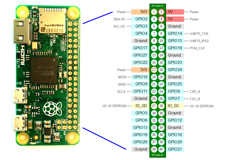
Raspberry Pi Zero W — pinout referenceRaspberry Pi Zero W — referencia de pinout
Print this or keep it open in a tab while you wire — every pin number, GPIO label, and alt-function (UART, I²C, SPI) at a glance. Imprime esto o mantenlo abierto en una pestaña mientras cableas — cada número de pin, etiqueta GPIO y función alternativa (UART, I²C, SPI) de un vistazo.