Rover 1 — Build ManualRover 1 — Manual de Armado
Step-by-step guide to wire up your RobotiMaker small-car kit. Click any pin or wire row to highlight it on the diagram.Guía paso a paso para cablear tu kit de coche RobotiMaker. Haz clic en cualquier pin o cable para resaltarlo en el diagrama.
What's in the boxQué hay en la caja
Orientation — front, rear, left, rightOrientación — frente, trasera, izquierda, derecha
Read this before Stage 1. Every wiring instruction in the manual uses "left" and "right" — and "left" only makes sense once you've picked which side of the rover is the front. Pick wrong and everything still works, but the joystick will be backwards.Lee esto antes de la Etapa 1. Cada instrucción de cableado en el manual usa "izquierda" y "derecha" — y "izquierda" sólo tiene sentido una vez que has decidido qué lado del rover es el frente. Si lo eliges mal todo seguirá funcionando, pero el joystick estará invertido.

How to identify each sideCómo identificar cada lado
| SideLado | How to identify itCómo identificarlo |
|---|---|
| FRONT | The side with the camera shell (rounded module with the lens). The status LEDs are also on this end. This is the direction the rover drives when you push the joystick forward.El lado con la carcasa de la cámara (módulo redondeado con el lente). Los LEDs de estado también están en este extremo. Es la dirección en la que el rover avanza cuando empujas el joystick hacia adelante. |
| REAR | The opposite end. Has the blank shell (no camera). The power button sits on top toward this end.El extremo opuesto. Tiene la carcasa lisa (sin cámara). El botón de encendido va arriba hacia este extremo. |
| LEFT | Stand behind the rover looking the same way it drives (toward the camera). The track on your left hand is the LEFT side. Motors here are the A pair (TB6612 AO1/AO2, controlled by Pico GP0/GP1/GP2).Párate detrás del rover mirando en la misma dirección en que avanza (hacia la cámara). La oruga que queda a tu mano izquierda es el lado IZQUIERDO. Los motores de este lado son el par A (TB6612 AO1/AO2, controlados por la Pico GP0/GP1/GP2). |
| RIGHT | The opposite track. Motors here are the B pair (TB6612 BO1/BO2, controlled by Pico GP3/GP4/GP5).La oruga opuesta. Los motores de este lado son el par B (TB6612 BO1/BO2, controlados por la Pico GP3/GP4/GP5). |
Why this matters for wiringPor qué importa para el cableado
In Stage 1 you wire the four motors into two pairs (FL+RL together as the A pair, FR+RR together as the B pair). If you swap which physical side is the A pair, the rover still drives — but pushing "forward" on the joystick will spin the tracks in the wrong direction, or steer left when you want right.En la Etapa 1 cableas los cuatro motores en dos pares (FL+RL juntos como par A, FR+RR juntos como par B). Si intercambias qué lado físico es el par A, el rover seguirá funcionando — pero empujar "adelante" en el joystick hará girar las orugas en la dirección equivocada, o girará a la izquierda cuando quieras ir a la derecha.
The simple ruleLa regla simple
- Wire the side with the camera as FRONT. The camera always faces the direction the rover is moving when you push forward on the joystick.Cablea el lado con la cámara como FRENTE. La cámara siempre apunta en la dirección en la que el rover se mueve cuando empujas el joystick hacia adelante.
- A pair = LEFT side. When looking from behind the rover (same direction it drives), your left hand is the A side.Par A = lado IZQUIERDO. Mirando desde atrás del rover (en la misma dirección en que avanza), tu mano izquierda corresponde al lado A.
- B pair = RIGHT side. The other track.Par B = lado DERECHO. La otra oruga.
If the rover drives backwards / steers wrong after assemblySi el rover va al revés o gira mal después del armado
Don't redo the wiring — fix it in software. There are four "symptoms" and four fixes:No vuelvas a cablear — arréglalo por software. Hay cuatro "síntomas" y cuatro soluciones:
- Pushes forward but drives backwards: swap the AIN1/AIN2 wires and BIN1/BIN2 wires (both pairs).Empujas adelante pero va hacia atrás: intercambia los cables AIN1/AIN2 y BIN1/BIN2 (ambos pares).
- Pushes forward, only one side reverses: swap AIN1↔AIN2 only (left misaligned) or BIN1↔BIN2 only (right misaligned).Empujas adelante, sólo un lado se invierte: intercambia AIN1↔AIN2 (izquierda mal) o BIN1↔BIN2 (derecha mal).
- Left and right swapped (push right → goes left): you assembled the A pair on the wrong physical side. Swap the entire A and B wire bundles at the TB6612, OR rename them in the Pico firmware (left ↔ right).Izquierda y derecha invertidas (empujar derecha → va izquierda): ensamblaste el par A en el lado físico equivocado. Intercambia los grupos completos de cables A y B en el TB6612, O renómbralos en el firmware de la Pico (izquierda ↔ derecha).
- Camera is at the rear, not the front: physically rotate the chassis 180°. That's the only "wrong" orientation that's easier to fix mechanically than electrically — flip the shell and floor between front and back.La cámara está atrás, no adelante: rota el chasis 180° físicamente. Es la única orientación "incorrecta" más fácil de arreglar mecánicamente que eléctricamente — intercambia carcasa y piso entre frente y atrás.
Easier route: print one extra shell_blank and shell_rpi_camera if you change your mind about which end is the front.Ruta más fácil: imprime una pieza extra de shell_blank y shell_rpi_camera por si cambias de idea sobre qué extremo es el frente.
In the app, "forward" is always the camera's view direction. If you've assembled the rover correctly, this is automatic — push forward, the camera moves forward through the room.En la app, "adelante" siempre es la dirección hacia la que mira la cámara. Si armaste el rover correctamente, esto es automático — empuja adelante y la cámara avanza por la habitación.
Solder the motors to the TB6612Solda los motores al TB6612
Pair the two left motors and the two right motors so each side moves together. The reds and blacks of each pair join, then go to one TB6612 channel. Not sure which side is "left"? See the orientation reference first — the camera shell is the front, and "left" is the driver's left when looking the way the rover drives.Empareja los dos motores izquierdos y los dos derechos para que cada lado se mueva en conjunto. Los rojos y los negros de cada par se unen, y luego van a un canal del TB6612. ¿No sabes cuál lado es "izquierdo"? Mira primero la referencia de orientación — la carcasa de la cámara es el frente, e "izquierda" es la izquierda del conductor mirando en la dirección en que avanza el rover.
Read this BEFORE you solder — TT motors have no + / − markingsLee esto ANTES de soldar — los motores TT no traen marcas + / −
Your motors are "TT" type (yellow plastic dual-shaft gearmotors). They have two flat metal terminals on top, but neither is marked + or −. The terminal that becomes "+" is whichever one you solder the red wire to. And because the left and right motors are mirror-mounted in the chassis (their gearbox shafts point toward each other across the rover), wiring both sides the same way will make one side spin backwards.Tus motores son del tipo "TT" (motorreductores amarillos de plástico con doble eje). Tienen dos terminales metálicos planos arriba, pero ninguno está marcado como + o −. El terminal que se convierte en "+" es el que tú elijas para soldar el cable rojo. Y como los motores izquierdo y derecho están montados en espejo en el chasis (sus ejes apuntan uno hacia el otro a través del rover), cablear ambos lados igual hará que uno gire al revés.
The 30-second test that prevents all polarity headaches:La prueba de 30 segundos que evita todos los dolores de cabeza de polaridad:
- Mount the motor in its slot (FL, RL, FR or RR) so the wheel can spin freely.Monta el motor en su ranura (FL, RL, FR o RR) de modo que la rueda pueda girar libremente.
- Touch a single AA or AAA battery briefly to the two terminals — red dot of battery on one terminal, black on the other.Toca brevemente una pila AA o AAA en los dos terminales — el extremo rojo de la pila en un terminal y el negro en el otro.
- Watch which way the wheel spins. Imagine the whole rover driving forward.Observa hacia dónde gira la rueda. Imagina al rover entero avanzando.
- Wheel spins the "drive-forward" direction → solder the red wire to the terminal touched by the battery's +.La rueda gira en la dirección de "avance" → solda el cable rojo al terminal que tocó el + de la pila.
- Wheel spins backwards → swap the battery, then solder red to the terminal that gives forward rotation.La rueda gira al revés → invierte la pila y solda el rojo al terminal que da rotación hacia adelante.
- Solder the black wire to the other terminal.Solda el cable negro al otro terminal.
- Repeat for all four motors.Repite para los cuatro motores.
After this, all four motors will drive "forward" when fed +V — and the rover drives forward when the joystick says forward, no software inversion needed.Después de esto, los cuatro motores girarán "hacia adelante" cuando reciban +V — y el rover avanzará cuando el joystick diga adelante, sin necesidad de invertir nada por software.
| Wire | Motor | TB6612 pin |
|---|---|---|
| Red | Front left | A01 (joined w/ rear left red) |
| Red | Rear left | A01 (joined w/ front left red) |
| Black | Front left | A02 (joined w/ rear left black) |
| Black | Rear left | A02 (joined w/ front left black) |
| Red | Front right | B01 (joined w/ rear right red) |
| Red | Rear right | B01 (joined w/ front right red) |
| Black | Front right | B02 (joined w/ rear right black) |
| Black | Rear right | B02 (joined w/ front right black) |
Why pair them?¿Por qué emparejarlos?
The TB6612 has two channels (A & B). Each channel controls one "side" of the rover. Joining the two left motors together means they always spin in unison, same for the right pair — that's how 4-wheel skid steering works.El TB6612 tiene dos canales (A y B). Cada canal controla un "lado" del rover. Unir los dos motores izquierdos significa que siempre giran al unísono, igual con el par derecho — así funciona la dirección por deslizamiento de 4 ruedas.
Wire the Pico to the TB6612Cablea la Pico al TB6612
9 wires. The Pico tells the TB6612 which direction each side should spin and how fast. Click a row to see the matching wire.9 cables. La Pico le dice al TB6612 hacia qué dirección debe girar cada lado y a qué velocidad. Haz clic en una fila para ver el cable correspondiente.
| Pico pin | → TB6612 pin | Purpose |
|---|---|---|
| GP0 | AIN1 | Left motors direction |
| GP1 | AIN2 | Left motors direction |
| GP2 | PWMA | Left motors speed (PWM) |
| GP3 | BIN1 | Right motors direction |
| GP4 | BIN2 | Right motors direction |
| GP5 | PWMB | Right motors speed (PWM) |
| GP6 | STBY | Enable chip — must be HIGH |
| 3V3 | VCC | Logic power (3.3 V) |
| GND | GND | Common ground |
3 things to remember3 cosas para recordar
- STBY must be wired — without it the chip stays disabled and nothing moves.STBY tiene que estar cableado — sin él el chip queda deshabilitado y nada se mueve.
- VCC is logic power (3.3 V). VM is motor power (7.4 V from the battery — wired in stage 4). Don't mix them up.VCC es alimentación lógica (3.3 V). VM es alimentación de motores (7.4 V de la batería — se cablea en la etapa 4). No los confundas.
- GP2 and GP5 are the PWM pins — they control speed. The others (AIN1/AIN2, BIN1/BIN2) just set direction.GP2 y GP5 son los pines PWM — controlan la velocidad. Los demás (AIN1/AIN2, BIN1/BIN2) sólo fijan la dirección.
Common GND — what it actually isTierra común (GND) — qué es realmente
Throughout this manual you'll see "Common GND" everywhere. It's not a part you buy or a place on the chassis — it's a concept. This page explains what it means and how to build one.A lo largo de este manual verás "Tierra común" por todas partes. No es una pieza que se compra ni un lugar del chasis — es un concepto. Esta página explica qué significa y cómo construir una.
The idea in one sentenceLa idea en una frase
Every chip in the rover needs to agree on what 0 V means. "Common GND" means every GND pin in the system is electrically connected — through whatever path you choose. They don't all need to meet at one point; they just need to be on the same continuous chain of black wires.Cada chip del rover necesita ponerse de acuerdo sobre qué significa 0 V. "Tierra común" quiere decir que cada pin GND del sistema está conectado eléctricamente — por el camino que tú elijas. No todos tienen que juntarse en un único punto; sólo necesitan estar en la misma cadena continua de cables negros.
How most builders actually do it — daisy-chainCómo lo hace la mayoría — encadenado en serie
In practice, almost everyone daisy-chains the GND through the devices: the GND from one board jumps to the next, and the next, until everything is electrically the same node. It still counts as "common ground" — because all the GND pins are still connected, just through a chain of jumpers instead of a star.En la práctica casi todos encadenan la GND a través de los dispositivos: la GND de una placa salta a la siguiente, y a la siguiente, hasta que todo es eléctricamente el mismo nodo. Sigue siendo "tierra común" — porque todos los pines GND están conectados, sólo que a través de una cadena de jumpers en vez de una estrella.
Two physical ways to wire itDos formas físicas de cablearlo
Option A — Daisy-chain through devices ⭐ recommendedOpción A — Cadena entre dispositivos ⭐ recomendado
One short black jumper between each pair of adjacent devices, plus short branches for servo and switch LED. Cheaper, cleaner, fewer cables to route. Almost every DIY robotics build uses this. The "Pi pin 6 → Pico pin 38" wire in Stage 7 is exactly this pattern.Un jumper negro corto entre cada par de dispositivos adyacentes, más ramas cortas para el servo y el LED del interruptor. Más barato, más limpio, menos cables que rutear. Casi todo proyecto de robótica DIY lo hace así. El cable "Pi pin 6 → Pico pin 38" de la Etapa 7 es exactamente este patrón.
Option B — Star topology to a dedicated busOpción B — Topología en estrella a un bus dedicado
Solder a strip of female headers (or a small terminal block) onto a piece of perfboard. Run every black wire individually to the bus. More wires, but easier to test individual boards in isolation. Useful for prototyping when you'll be removing/swapping parts often.Solda una tira de cabeceras hembra (o una pequeña bornera) sobre un trozo de perfboard. Lleva cada cable negro de forma individual al bus. Más cables, pero más fácil probar cada placa aisladamente. Útil para prototipado cuando vas a quitar y poner partes a menudo.
The mental shortcutEl atajo mental
Whenever any wiring table in this manual says "Common GND", it means: this pin needs to end up electrically connected to all the other GND pins. It does not mean "run a fresh wire to a central bus." A short jumper to the nearest GND pin on the next board does the same job.Cuando una tabla de cableado de este manual dice "Tierra común", significa: este pin debe quedar eléctricamente conectado a todos los demás pines GND. No significa "llevar un cable nuevo a un bus central". Un jumper corto al pin GND más cercano de la siguiente placa hace exactamente lo mismo.
The most common rover build mistakeEl error más común al armar el rover
Breaking the chain. Symptom: motors twitch but won't turn smoothly, or the servo jitters, or the Pico can't see the Pi's UART signals. Fix: trace every black wire and confirm there's an unbroken electrical path from every GND pin back to the XT30 − terminal. If any board is "isolated" — its GND not reaching the others — that board floats and behaves randomly.Romper la cadena. Síntoma: los motores tiemblan pero no giran bien, el servo vibra, o la Pico no detecta las señales UART de la Pi. Solución: traza cada cable negro y confirma que hay un camino eléctrico continuo desde cada pin GND hasta el terminal − del XT30. Si alguna placa queda "aislada" — su GND no llega al resto — esa placa "flota" y se comporta de forma errática.
Set up the buck converterConfigura el convertidor reductor
The buck steps the 7.4 V battery down to 5 V — that powers the Pi Zero W and the servo. Set the voltage before connecting anything.El buck reduce los 7.4 V de la batería a 5 V — eso alimenta la Pi Zero W y el servo. Ajusta el voltaje antes de conectar nada.
Calibrate first
Connect the buck's IN+ / IN− to the battery (via the XT30 pigtail), hook a multimeter across OUT+ / OUT−, and turn the trim-pot until the meter reads 5.00 V ± 0.05. Only then plug anything else into OUT+/OUT−.
| Buck terminal | Goes to | Notes |
|---|---|---|
| IN+ | Switch L (switched battery +) | Red — wired up in Stage 4a |
| IN− | GND chain — short jumper from Switch LED− (or directly from XT30 −) | Black |
| OUT+ → branch 1 | Pi Zero W pin 2 (5V) | Red — splice with the servo wire |
| OUT+ → branch 2 | MG90S servo red | Red — splice with the Pi 5V wire |
| OUT− | GND chain — short jumper to Pi pin 6 (next link) | Black, often unused: most buck modules tie IN− and OUT− internally on the PCB |
Calibration trickTruco de calibración
For the multimeter calibration step above, you can temporarily power the buck directly from the XT30 + line (skip the switch). Once it reads 5.00 V cleanly, disconnect, then reroute through the switch as the table shows.Para el paso de calibración con el multímetro de arriba, puedes alimentar el buck temporalmente directo desde la línea + del XT30 (salta el interruptor). Cuando marque 5.00 V limpios, desconecta y re-rutea a través del interruptor como muestra la tabla.
The golden rule — one continuous GND chainLa regla de oro — una cadena GND continua
Every GND pin in the rover (XT30 −, buck IN−/OUT−, Pico, Pi, TB6612, servo, switch LED−) must end up electrically connected via the daisy-chain. You don't need to run a separate wire from each one to a central point — short jumpers between adjacent boards work fine. But if any board is missing from the chain, that board floats and the whole rover misbehaves. See the Common GND reference if this is unclear.Cada pin GND del rover (XT30 −, buck IN−/OUT−, Pico, Pi, TB6612, servo, LED− del interruptor) debe acabar conectado eléctricamente mediante la cadena en serie. No hace falta llevar un cable individual desde cada uno hasta un punto central — jumpers cortos entre placas adyacentes funcionan bien. Pero si alguna placa queda fuera de la cadena, esa placa "flota" y todo el rover se comporta mal. Mira la referencia de Tierra Común si esto no está claro.
Power switch (5-pin illuminated metal push-button)Interruptor de encendido (pulsador metálico iluminado de 5 pines)
A 19 mm latching metal push-button sits between the battery's positive terminal and the rest of the circuit. Press once — the LED ring lights up and the rover wakes. Press again — power off. Five terminals on the back: three for the switch contacts and two for the LED.Un pulsador metálico enclavado de 19 mm va entre el terminal positivo de la batería y el resto del circuito. Una pulsación — el aro LED se enciende y el rover despierta. Otra pulsación — apagado. Cinco terminales atrás: tres para los contactos del interruptor y dos para el LED.
| Wire | From | To | Purpose |
|---|---|---|---|
| Red | XT30 + | Switch COM (battery in) | Power into the switch's common contact |
| Red | Switch NO (normally-open contact) | Buck IN+ + TB6612 VM | Switched output — closed when latched on, feeds the whole rover |
| Yellow | Switch LED+ | Switch NO (same point as the load) | Lights the LED ring only while the button is pressed in (ON) |
| Grey | Switch LED− | GND chain (next link → Buck IN−) | LED return path; also continues the GND chain |
| Black | XT30 − | Switch LED− (first link of the GND chain — bypasses the switch contacts) | Starts the chain from the battery — never run this through the switch |
| — | Switch NC (normally-closed) | Unused | Leave open. NC is the inverse of NO — closed when the button is OFF — and we don't need that for a simple master switch |
Never switch the GND lineNunca interrumpas la línea GND con el interruptor
The switch only interrupts positive. The negative rail must run uninterrupted from the XT30 − line to the common ground. Switching ground breaks the shared reference between the Pi, Pico, motor driver, and servo — at best nothing works, at worst you fry the logic chips.El interruptor sólo interrumpe el positivo. El raíl negativo tiene que ir ininterrumpido desde el − del XT30 hasta la tierra común. Cortar la tierra rompe la referencia compartida entre Pi, Pico, controlador de motores y servo — en el mejor caso nada funciona, en el peor quemas los chips lógicos.
Make sure you have a LATCHING button (not momentary)Asegúrate de tener un pulsador ENCLAVADO (no momentáneo)
The same physical body is sold in two flavours. Latching (self-locking) stays in whichever position you push it into — press once for ON, press again for OFF. Momentary (self-reset) springs back the instant you let go — useless for a master power switch.El mismo cuerpo físico se vende en dos versiones. Enclavado (auto-bloqueante) se queda en la posición en que lo pones — una pulsación enciende, otra apaga. Momentáneo (auto-retorno) vuelve solo al soltarlo — inútil para un interruptor maestro.
- Multimeter on continuity beep across the two switch pins. Press and release the button.Multímetro en continuidad (pitido) entre los dos pines del interruptor. Pulsa y suelta el botón.
- If the meter beeps only while pressed → momentary. Don't use it for this stage.Si pita sólo mientras lo pulsas → momentáneo. No lo uses para esta etapa.
- If the meter beeps after one press and stays beeping until you press again → latching. ✓Si pita después de una pulsación y sigue pitando hasta que vuelvas a pulsar → enclavado. ✓
Pin labels vary — verify with a multimeterLas etiquetas de los pines varían — verifica con un multímetro
Some buttons print labels on the back (NC · C · NO · + · −), some only stamp numbers, some are blank. Universal test:Algunos pulsadores traen etiquetas atrás (NC · C · NO · + · −), otros sólo números, otros nada. Prueba universal:
- Set the multimeter to continuity beep. With the button pressed on, probe pairs of the three large pins. The one pair that beeps = COM and NO (either way round for our wiring — both carry the load when ON).Pon el multímetro en continuidad. Con el botón pulsado, prueba pares entre los tres pines grandes. El par que pita = COM y NO (cualquier orden sirve para nuestro cableado — ambos llevan la carga cuando está ON).
- Release the button. The pair that beeps now is COM + NC — you'll leave that NC pin unconnected.Suelta el botón. El par que pita ahora es COM + NC — ese pin NC se queda sin conectar.
- The remaining two pins are the LED. Identify polarity with a 3 V coin cell + 1 kΩ resistor — whichever orientation lights the ring is correct. The + side is LED+, the other is LED−.Los dos pines restantes son el LED. Identifica la polaridad con una pila de botón de 3 V + resistor de 1 kΩ — la orientación que encienda el aro es la correcta. El lado + es LED+, el otro es LED−.
Mount the button on the top or side of the chassis where it's easy to reach without flipping the rover. The 19 mm hole takes 30 seconds to drill — secure with the supplied nut on the inside. Keep the XT30 + wire between battery and switch as short as possible — it's always live, even when the button is off. Best practice: unplug the XT30 entirely when the rover is stored.Monta el pulsador arriba o al costado del chasis donde sea fácil de alcanzar sin voltear el rover. El agujero de 19 mm se hace en 30 segundos — fija con la tuerca incluida por dentro. Mantén el cable + del XT30 entre la batería y el interruptor lo más corto posible — siempre está vivo, aunque el botón esté apagado. Mejor práctica: desconecta el XT30 del todo cuando guardes el rover.
Battery → motor powerBatería → alimentación de motores
One thick red wire from the switched output (Switch L) to the TB6612's VM pin. That's the high-current path that drives the tracks. The TB6612's GND already reaches the rest of the system through the daisy-chain you set up earlier — no separate GND wire to the battery is needed here.Un cable rojo grueso desde la salida conmutada (interruptor L) hasta el pin VM del TB6612. Esa es la vía de alta corriente que mueve las orugas. El GND del TB6612 ya llega al resto del sistema mediante la cadena que armaste antes — no hace falta otro cable de GND directo a la batería.
| Wire | From | To |
|---|---|---|
| Red | Switch L (switched +) | TB6612 VM |
Use thicker wire here than the logic wires (e.g. 22 AWG vs 26 AWG) — this single wire carries several hundred mA per motor.Usa aquí cable más grueso que en los cables lógicos (p. ej. 22 AWG vs 26 AWG) — este único cable lleva varios cientos de mA por motor.
What about TB6612 GND?¿Y el GND del TB6612?
It's already connected. The TB6612's GND pin is reached through the GND daisy-chain — specifically the Pico pin 38 → TB6612 GND jumper (link G6 in the Full wiring diagram). Adding a second wire from XT30 − directly to TB6612 GND is unnecessary and would just create a parallel return path.Ya está conectado. El pin GND del TB6612 se alcanza por la cadena de GND — concretamente con el jumper Pico pin 38 → TB6612 GND (enlace G6 en el diagrama Cableado completo). Añadir un segundo cable desde el − del XT30 directo al GND del TB6612 es innecesario y sólo crea un camino de retorno paralelo.
How many wires leave the XT30 in total?¿Cuántos cables salen del XT30 en total?
- XT30 + — one red wire out, going to Switch "Positive" (battery in)XT30 + — un cable rojo de salida, hacia el "Positivo" del interruptor (entrada de batería)
- XT30 − — one black wire out, starting the GND daisy-chain (first link goes to Switch LED−; everything downstream is tied through that chain)XT30 − — un cable negro de salida, iniciando la cadena de GND (el primer enlace va al LED− del interruptor; todo lo demás se conecta a través de esa cadena)
Total wires from the battery side: two. The Switch's L pin is what splits to feed both Buck IN+ and TB6612 VM — that split happens after the switch, not at the battery.Total de cables desde el lado de la batería: dos. El pin L del interruptor es el que se divide para alimentar IN+ del buck y VM del TB6612 — esa derivación ocurre después del interruptor, no en la batería.
Servo & gimbalServo y soporte
The MG90S tilts the camera. 3 wires: power, ground, signal.El MG90S inclina la cámara. 3 cables: alimentación, tierra, señal.
| Servo wire | Goes to |
|---|---|
| Red | Buck OUT+ (5 V) — splice with the Pi 5V wire |
| Brown / Black | GND chain — branch off any nearby chain link (Buck OUT− or Pi pin 6) |
| Orange / Yellow | Pi Zero W GPIO 12 (pin 32) |
Power the Pi Zero WAlimenta la Pi Zero W
From the buck's 5 V output to the Pi's GPIO header. Skip the micro-USB jack — feeding through the header is cleaner and more reliable.Desde la salida de 5 V del buck hasta el header GPIO de la Pi. Olvida el conector micro-USB — alimentar por el header es más limpio y fiable.
| WireCable | FromDesde | ToHasta |
|---|---|---|
| RedRojo | Buck OUT+ | Pi Zero W pin 2 (5V) |
| BlackNegro | Buck OUT− | Pi Zero W pin 6 (GND) |
Pi ↔ Pico — GPIO link (no USB)Pi ↔ Pico — enlace por GPIO (sin USB)
The Pico is now powered by the Pi and talks to it over UART (serial). 4 wires total — power, ground, TX/RX. No USB cable needed.Ahora la Pico se alimenta desde la Pi y se comunica por UART (serie). 4 cables en total — alimentación, tierra, TX/RX. Sin necesidad de cable USB.
| From (Pi Zero W) | To (Pico) | Purpose |
|---|---|---|
| 5V — pin 4 | VSYS — pin 39 | Powers the Pico from the Pi rail |
| GND — pin 6 | GND — pin 38 | Common ground |
| GPIO14 / TXD — pin 8 | GP9 / UART1 RX — pin 12 | Pi sends → Pico receives |
| GPIO15 / RXD — pin 10 | GP8 / UART1 TX — pin 11 | Pico sends → Pi receives |
Why GPIO instead of USB?
Direct UART over GPIO is faster to wire, frees the Pi's only USB port for other things (e.g. a Wi-Fi dongle), and removes one point of failure (the USB cable). Since the Pi is already powered, sharing 5 V with the Pico over a single jumper is trivial.
One-time Pi config
Enable the serial port on the Pi: sudo raspi-config → Interface Options → Serial Port → "No" to login shell over serial, "Yes" to serial port hardware. Reboot. The Pi can then read/write /dev/serial0 at 115200 baud.
CameraCámara
A flexible CSI ribbon plugs into the Pi Zero W's small camera connector. Pay attention to orientation — wrong way and there's no signal.Un cable plano CSI flexible va al pequeño conector de cámara de la Pi Zero W. Cuida la orientación — si va al revés no hay señal.
| ConnectionConexión | DetailDetalle |
|---|---|
| CSI ribbonCable CSI | Blue side of the cable faces the USB ports on the Pi Zero W. Lift the small black tab on the connector, slide ribbon all the way in, push the tab back down to lock.El lado azul del cable mira hacia los puertos USB de la Pi Zero W. Levanta la pequeña pestaña negra del conector, mete el cable hasta el fondo y baja la pestaña para fijarlo. |
| Camera endLado de la cámara | Same orientation — blue side faces away from the camera lens.Misma orientación — el lado azul mira en sentido opuesto al lente. |
Hardware done — one more thingHardware listo — una cosa más
Plug in the XT30 connector and press the metal button to power on — the LED ring lights up and the latch holds it in. The Pi boots in ~30 s. To actually drive the rover, you need to install the RobotiMaker bridge and pair the rover to your account — that's Stage 9.Conecta el XT30 y pulsa el botón metálico para encender — el aro LED se ilumina y queda enclavado. La Pi arranca en ~30 s. Para controlar el rover necesitas instalar el bridge de RobotiMaker y emparejar el rover a tu cuenta — eso es la Etapa 9.
Bring your rover online via the RobotiMaker appPon tu rover en línea mediante la app RobotiMaker
All wired up and powered on? Time to introduce the rover to the RobotiMaker app. The app docs walk you through this step by step — this section just summarises the path and links straight to the right pages.¿Todo cableado y encendido? Hora de presentarle el rover a la app RobotiMaker. La documentación de la app te guía paso a paso — esta sección sólo resume el camino y enlaza directamente a las páginas correspondientes.
Follow these in orderSigue estos pasos en orden
- Sign in to the app at app.robotimaker.ai. New here? See App docs → Getting started. Inicia sesión en la app en app.robotimaker.ai. ¿Es tu primera vez? Mira Docs de la app → Primeros pasos.
- Add the Pi as a bridge — three ways are documented in the app docs; for Crawler One the SD-flash wizard is the easiest if you have a fresh card, otherwise the SSH installer works on any Pi that's already online. Añade la Pi como bridge — las tres formas están documentadas en las docs de la app; para Crawler One el asistente de flasheo SD es lo más fácil si tienes una tarjeta nueva, si no, el instalador por SSH funciona en cualquier Pi que ya esté en línea.
- Once the bridge shows Online, create a robot pointing at it via the create-robot wizard. Pick Robotics → Wheeled Car and choose the bridge you just added. Cuando el bridge aparezca Online, crea un robot que lo apunte con el asistente de creación de robot. Elige Robotics → Coche con ruedas y selecciona el bridge que acabas de añadir.
- Open the robot's dashboard. You'll see the live camera preview and the joystick — drive it for the first time. Abre el panel del robot. Verás la vista previa de la cámara y el joystick — condúcelo por primera vez.
That's all there is — the bridge reconnects automatically on every boot, you won't have to repeat this. Eso es todo — el bridge se reconecta automáticamente en cada arranque, no tendrás que repetir esto.
If pairing times outSi el emparejamiento expira
The app gives the bridge about three minutes to phone in. If it doesn't, check on the Pi: systemctl status buildyourrobot-bridge — the unit should be active (running). If it's failing, journalctl -u buildyourrobot-bridge -n 50 usually shows why (wrong WiFi creds, no network, stale install).La app le da unos tres minutos al bridge para reportarse. Si no lo hace, revisa en la Pi: systemctl status buildyourrobot-bridge — el unit debe estar active (running). Si falla, journalctl -u buildyourrobot-bridge -n 50 suele mostrar por qué (credenciales WiFi malas, sin red, instalación obsoleta).
If the rover doesn't move when you push the joystickSi el rover no se mueve al empujar el joystick
The bridge is online but the Pi isn't talking to the Pico. Re-check Stage 7 — the UART crossover (Pi TX → Pico RX, Pi RX → Pico TX) and the shared GND link. Also confirm the power switch is latched ON so the buck converter is actually delivering 5 V to the motor side.El bridge está en línea pero la Pi no se comunica con la Pico. Revisa la Etapa 7 — el cruce UART (Pi TX → Pico RX, Pi RX → Pico TX) y el enlace de GND compartido. Confirma también que el interruptor de encendido está enclavado en ON para que el buck esté entregando 5 V al lado de los motores.
Pi Zero W — every connectionPi Zero W — todas las conexiones
Every pin and connector on the Raspberry Pi Zero W that this build uses, in one diagram. Use this when you want to see the Pi's complete wiring picture without flipping between Stages 5, 6, 7, and 8.Cada pin y conector de la Raspberry Pi Zero W que usa esta build, en un solo diagrama. Úsalo cuando quieras ver el panorama completo del cableado de la Pi sin saltar entre las Etapas 5, 6, 7 y 8.
| Pi pin | Function | Goes to | Stage |
|---|---|---|---|
| pin 2 — 5V | Power IN (this is what feeds the Pi) | Buck OUT+ | Stage 6 |
| pin 4 — 5V | Power OUT (same 5 V rail, used to feed the Pico) | Pico VSYS — pin 39 | Stage 7 |
| pin 6 — GND | Ground (chain link in the daisy) | Pico pin 38 (next link); also branches to Servo brown | Stage 7 + chain |
| pin 8 — GPIO 14 / TXD | UART TX — Pi sends to Pico | Pico GP9 / RX — pin 12 | Stage 7 |
| pin 10 — GPIO 15 / RXD | UART RX — Pi receives from Pico | Pico GP8 / TX — pin 11 | Stage 7 |
| pin 32 — GPIO 12 | PWM signal for camera servo | MG90S servo orange wire | Stage 5 |
| CSI ribbon | Camera serial interface | Pi Camera v1.3 / v2 | Stage 8 |
The Pi Zero W in one sentenceLa Pi Zero W en una frase
It's the main brain: it runs the RobotiMaker bridge service, streams live video from the camera back to the app, sends motor commands to the Pico over UART, drives the servo directly via GPIO 12, and feeds 5 V power back out to the Pico.Es el cerebro principal: corre el servicio del bridge RobotiMaker, transmite el video en vivo de la cámara hacia la app, envía comandos de motor a la Pico por UART, controla el servo directamente por GPIO 12 y devuelve 5 V de alimentación hacia la Pico.
What about pin 1 (3V3)?¿Y el pin 1 (3V3)?
Pin 1 is not used in this build. The TB6612's 3.3 V logic supply comes from the Pico's pin 36 (3V3 OUT) instead — see the Pico reference. Both chips are physically near each other, so routing 3.3 V from the Pico keeps the high-current 3.3 V trace short and frees up the Pi's pin 1 for any future expansion.El pin 1 no se usa en esta build. La alimentación lógica de 3.3 V del TB6612 viene en cambio del pin 36 (3V3 OUT) de la Pico — mira la referencia de la Pico. Ambos chips están físicamente cerca, así que llevar 3.3 V desde la Pico mantiene corta la traza de 3.3 V y libera el pin 1 de la Pi para futuras expansiones.
Pin counting on the Pi Zero WCómo contar pines en la Pi Zero W
Hold the board with the SD-card slot at the top. The 40-pin GPIO header runs down the right edge. Pin 1 is the corner of the header closest to the SD-card slot. Pins are numbered: odd numbers down the left column of the header (1, 3, 5…), even numbers down the right column (2, 4, 6…). Pin 40 is at the bottom corner, opposite pin 1.Sostén la placa con la ranura microSD arriba. El header GPIO de 40 pines baja por el borde derecho. El pin 1 es la esquina del header más cercana a la ranura microSD. Los pines se numeran: impares en la columna izquierda del header (1, 3, 5…), pares en la columna derecha (2, 4, 6…). El pin 40 está en la esquina inferior, frente al pin 1.
Raspberry Pi Pico — every connectionRaspberry Pi Pico — todas las conexiones
Every pin on the Pico that this build uses, in one diagram. The Pico is the motor MCU — it does PWM, direction, and reads commands from the Pi over UART.Cada pin de la Pico que usa esta build, en un solo diagrama. La Pico es el microcontrolador de los motores — hace PWM, dirección y lee comandos de la Pi por UART.
| Pico pin | Function | Goes to | Stage |
|---|---|---|---|
| pin 39 — VSYS | Power IN (5 V from Pi) | Pi Zero W pin 4 | Stage 7 |
| pin 38 — GND | Ground (chain link) | Pi pin 6 ← upstream; TB6612 GND → downstream | Stage 7 + chain |
| pin 36 — 3V3 OUT | Logic-power output (3.3 V from Pico's onboard regulator) | TB6612 VCC | Stage 2 |
| pin 1 — GP0 | AIN1 — left motor direction line | TB6612 AIN1 | Stage 2 |
| pin 2 — GP1 | AIN2 — left motor direction line | TB6612 AIN2 | Stage 2 |
| pin 4 — GP2 | PWMA — left motor pair speed (PWM) | TB6612 PWMA | Stage 2 |
| pin 5 — GP3 | BIN1 — right motor direction line | TB6612 BIN1 | Stage 2 |
| pin 6 — GP4 | BIN2 — right motor direction line | TB6612 BIN2 | Stage 2 |
| pin 7 — GP5 | PWMB — right motor pair speed (PWM) | TB6612 PWMB | Stage 2 |
| pin 9 — GP6 | STBY — standby enable (must be HIGH for the chip to drive) | TB6612 STBY | Stage 2 |
| pin 11 — GP8 / UART1 TX | UART TX — Pico sends to Pi | Pi pin 10 (RXD) | Stage 7 |
| pin 12 — GP9 / UART1 RX | UART RX — Pico receives from Pi | Pi pin 8 (TXD) | Stage 7 |
The Pico in one sentenceLa Pico en una frase
It's the motor MCU: it generates the PWM signals that control speed (PWMA, PWMB), drives the direction logic for both motor pairs (AIN1/2, BIN1/2), feeds the TB6612 its 3.3 V logic supply (pin 36), and listens to the Pi over UART for "go forward at 50%" / "turn right" type commands. The Pi never talks to the TB6612 directly — the Pico is the translator.Es el microcontrolador de motores: genera las señales PWM que controlan la velocidad (PWMA, PWMB), maneja la lógica de dirección de ambos pares de motores (AIN1/2, BIN1/2), alimenta los 3.3 V lógicos del TB6612 (pin 36) y escucha a la Pi por UART comandos del tipo "avanza al 50%" / "gira a la derecha". La Pi nunca habla directamente con el TB6612 — la Pico es la traductora.
Pin counting on the PicoCómo contar pines en la Pico
Hold the board with the USB connector at the top. Pin 1 is the top-left pin (just below the USB on the left edge). Pins 1–20 run down the left side, then 21–40 wrap around — pin 21 is bottom-right, pin 40 is top-right. The BOOTSEL button (silver square in the middle) and the green LED give you visual landmarks.Sostén la placa con el conector USB arriba. El pin 1 es el de arriba a la izquierda (justo bajo el USB en el borde izquierdo). Los pines 1–20 bajan por la izquierda, luego 21–40 dan la vuelta — pin 21 abajo a la derecha, pin 40 arriba a la derecha. El botón BOOTSEL (cuadrado plateado en el centro) y el LED verde te sirven de referencias visuales.
Full system wiring — final checkCableado completo del sistema — revisión final
Every component, every wire, in one diagram. Use this to confirm everything is in place before you flip the switch. Wires are colour-coded: red = battery / 5 V, yellow = switched + (after switch), grey = GND, orange = control signals, blue = UART, purple = camera CSI.Cada componente, cada cable, en un solo diagrama. Úsalo para confirmar que todo está en su lugar antes de accionar el interruptor. Los cables van por colores: rojo = batería / 5 V, amarillo = + conmutado (tras el interruptor), gris = GND, naranja = señales de control, azul = UART, púrpura = CSI de cámara.
Wire-by-wire verification checklistChecklist de verificación cable por cable
Walk through each row before powering on. Tick each one as you trace it on your physical build.Repasa cada fila antes de encender. Marca cada una a medida que la trazas en tu build físico.
| # | Wire | From | To |
|---|---|---|---|
| 1 | Red | XT30 + (battery) | Switch B |
| 2 | Red | Switch L | Buck IN+ |
| 3 | Red | Switch L (same point) | TB6612 VM (motor power) |
| 4 | Yellow | Switch LED+ | Switch L (loopback) |
| 5 | Red | Buck OUT+ | Pi pin 2 (5V) |
| 6 | Red | Buck OUT+ (same point) | MG90S servo red |
| 7 | Red | Pi pin 4 (5V) | Pico pin 39 (VSYS) |
| 8 | Red | Pico pin 36 (3V3 OUT) | TB6612 VCC |
| 9 | Blue | Pi pin 8 (TX) ↔ pin 10 (RX) | Pico GP9 (RX) ↔ GP8 (TX) (cross-wired) |
| 10 | Orange | Pi GPIO 12 (pin 32) | MG90S servo signal |
| 11 | Orange | Pico (7 control pins) | TB6612 (PWMA, PWMB, AIN1, AIN2, BIN1, BIN2, STBY) |
| 12 | CSI ribbon | Pi camera connector | Pi Camera v1.3 / v2 |
| 13 | Red | TB6612 AO1 / AO2 | LEFT motor pair |
| 14 | Red | TB6612 BO1 / BO2 | RIGHT motor pair |
| G1 | Black | XT30 − | Switch LED− |
| G2 | Black | Switch LED− | Buck IN− |
| G3 | Black (dashed) | Buck IN− | Buck OUT− (often tied internally on the buck PCB — verify with a multimeter; only run a wire if the IN− and OUT− pads aren't continuous) |
| G4 | Black | Buck OUT− | Pi pin 6 (GND) |
| G5 | Black | Pi pin 6 (GND) | Pico pin 38 (GND) (this IS the Stage 7 wire) |
| G6 | Black | Pico pin 38 (GND) | TB6612 GND |
| G7 | Black | GND chain (branch tap near buck) | Servo brown |
Wire counts at a glanceConteo de cables de un vistazo
- 14 power / signal wires (red, yellow, orange, blue, purple)14 cables de potencia / señal (rojo, amarillo, naranja, azul, púrpura)
- 6–7 GND jumpers daisy-chained between adjacent boards (G3 is often unnecessary because most buck modules tie IN− and OUT− together internally)6–7 jumpers de GND encadenados entre placas adyacentes (G3 suele no hacer falta porque la mayoría de módulos buck unen IN− y OUT− internamente)
- Of the 14 power/signal wires, row 11 is a bundle of 7 individual jumpers (Pico ↔ TB6612 control). Same for row 9 (UART = 2 jumpers) and rows 13–14 (motor outputs = 2 jumpers each).De los 14 cables de potencia/señal, la fila 11 es un grupo de 7 jumpers individuales (control Pico ↔ TB6612). Lo mismo con la fila 9 (UART = 2 jumpers) y las filas 13–14 (salidas de motor = 2 jumpers cada una).
- True total individual jumpers: roughly 32 wires + 1 CSI ribbon. About a third less than the star topology — and the chassis stays much cleaner.Total real de jumpers individuales: aproximadamente 32 cables + 1 cable CSI. Cerca de un tercio menos que la topología en estrella — y el chasis queda mucho más limpio.
Pre-flight check before flipping the switchComprobación previa antes de encender
- Every GND pin is part of one continuous chain — whether you daisy-chained through the boards (recommended) or fanned everything to a bus, you should be able to trace an unbroken black-wire path from any GND pin all the way back to the XT30 −.Cada pin GND está dentro de una cadena continua — sea encadenado entre placas (recomendado) o llevado todo a un bus, debes poder trazar un camino ininterrumpido de cable negro desde cualquier pin GND hasta el − del XT30.
- VM ≠ VCC — VM is 7.4 V from the switch, VCC is 3.3 V from the Pico's pin 36 (3V3 OUT). Mixing them fries the TB6612.VM ≠ VCC — VM son 7.4 V desde el interruptor, VCC son 3.3 V desde el pin 36 (3V3 OUT) de la Pico. Confundirlos quema el TB6612.
- UART is cross-wired — Pi TX → Pico RX, Pi RX → Pico TX. Same-side wiring is a common silent failure.El UART va cruzado — Pi TX → Pico RX, Pi RX → Pico TX. Cablear del mismo lado es una falla silenciosa común.
- Buck output is set to 5.00 V ± 0.05 with a multimeter before connecting the Pi or servo to OUT+.La salida del buck está a 5.00 V ± 0.05 medida con multímetro antes de conectar la Pi o el servo al OUT+.
- Camera ribbon orientation: blue side faces the USB ports on the Pi, blue side faces away from the lens on the camera.Orientación del cable de la cámara: el lado azul mira hacia los puertos USB de la Pi, y el lado azul mira en sentido opuesto al lente en la cámara.
- Battery polarity at the XT30: + and − match before plugging in. XT30 connectors are keyed but can be soldered backwards.Polaridad de la batería en el XT30: + y − coinciden antes de enchufar. Los conectores XT30 tienen forma específica pero se pueden soldar al revés.
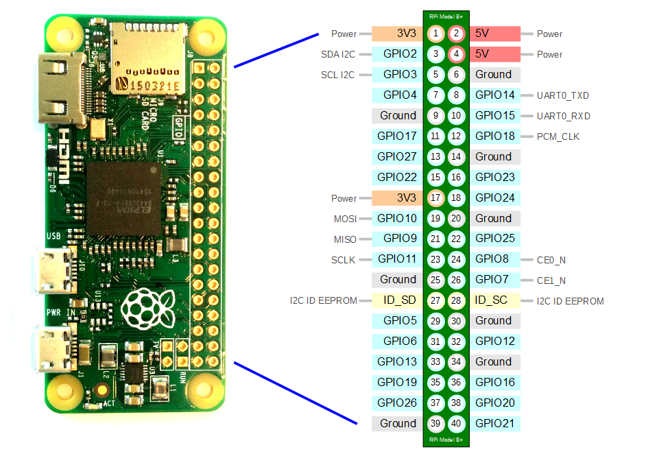
Raspberry Pi Zero W — pinout referenceRaspberry Pi Zero W — referencia de pinout
Print this or keep it open in a tab while you wire — every pin number, GPIO label, and alt-function (UART, I²C, SPI) at a glance. Imprime esto o mantenlo abierto en una pestaña mientras cableas — cada número de pin, etiqueta GPIO y función alternativa (UART, I²C, SPI) de un vistazo.